
Model building blocks#
The hydro module#
The hydropower system is described using standard modules linked via water routes for plant discharge, bypass and spillage. The links between the modules in a watercourse are established by declaring which lower positioned module receives plant discharge, bypass discharge and overflow. These can go to different modules. A module can consist of a reservoir with storable and non-storable inflow, and a power plant, see figure. 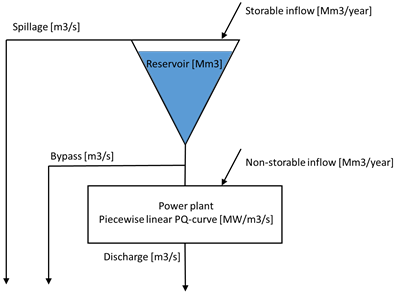
The reservoir is described by its volume. In addition, the relation between filling and elevation (reservoir curve) can be given as a piecewise linear curve. The reservoir curve is used when running Prodrisk with head computation and to estimate pump capacities. Two types of reservoirs are considered, the regulation reservoir and the buffer reservoir. The regulation reservoir is scheduled using cuts in Prodrisk. Currently, the lower limit of a regulation reservoir is 2.0 Mm3. The buffer reservoirs are operated by reservoir guideline curves. They will deviate from their guideline curve only when constraints cause it to be necessary. The buffer reservoirs are often small intake ponds, which, as an example, must keep a head to the plant positioned below.
The power plant, or possibly the gate, the river or the stream intake (i.e., no generation), is described by its rated discharge and energy conversion factor. For plants, the relation between generation and discharge (piecewise linear curve) is normally given with a reference head. The resulting generation for a given discharge is compensated according to the actual head.
A module can have inflow that can both be stored in the reservoir (storable) and flow directly to the plant (non-storable). The inflow is quoted by its annual mean and is linked to an inflow record (gauging station). Inflow records should be specified with either daily or weekly time resolution.
The following constraints can be specified for a hydropower module:
Max reservoir volume (absolute or local)
Min reservoir volume (absolute or local)
Max discharge (curve or inflow series)
Min discharge (curve or inflow series)
Max bypass (value)
Min bypass (curve or inflow series)
All constraints are soft in the sense that they can be violated subject to a penalty. The use of penalty values are described in Penalty values in straff.CPAR.
Constraints on reservoir volume can be given as absolute or local. The absolute constraints should be met by the system as a whole. For example, any upstream reservoir can release water to make sure that a downstream minimum reservoir constraint is met. The local constraints should only use the local reservoir to meet its reservoir limits. For example, a local minimum reservoir constraint should limit release from the local reservoir, but should not impact the operation of the upstream reservoirs. NB! Prodrisk converts the local minimum reservoir-volume constraints to absolute ones, taking into account the expected availability of “local” water.
They can all be time-dependent. In addition, the constraints on discharge and bypass can be linked to inflow records. Prodrisk does not include head-dependent maximum discharge when computing the strategy.
A pump is described with a relation between head and max amount of pumped water, the power needed to pump and its position in the watercourse (what reservoir it pumps to and from). Two types of pumps can be specified:
Pumped storage plant: A hydropower plant that can reverse its turbines in order to pump water up to the reservoir positioned above in periods with low load and/or high inflow rate.
Pumping station: A pump only, whose task typically is to pump water to another reservoir where the water can be better used in energy generation.
What is called reservoirs and plants with hydraulic coupling in the model, will, when used, achieve a significantly greater flexibility in the modelling of watercourses than the standard modules allow for. Prodrisk allows hydraulic couplings, but will not be able to prevent the water flowing towards a higher altitude.