
Hydraulic coupling in Prodrisk#
The hydraulic coupling in Prodrisk is similar to the hydraulic coupling described in the EOPS documentation, but comes with minor modifications and will therefore be described in this article. The use of hydraulic coupled modules can provide a significantly larger flexibility in modelling of a watercourse than what standard modules provide. In Prodrisk there are 3 types of hydraulic coupled modules, decided by the parameter KODE. In the command line interface (CLI), there are three parameters that are concerned for each module/reservoir:
Parameter 9 - KODE for hydraulic coupling
Parameter 10 - Coupling number
Parameter 11 - Flow capacity between coupled reservoirs (configuration 2 and 3)
The maximum number of hydraulic coupled systems is 10 and every hydraulic coupled system can contain 10 reservoirs.
The disadvantage of using hydraulic coupling is that you can have different water values despite the coupling between reservoirs, and water may flow from a reservoir with lower head to a reservoir with higher head if that is economically optimal.
Configuration 1: Reservoirs coupled to a common station#
In this configuration, 2 or more reservoirs are coupled to a common station. Flow directly between the reservoirs is not allowed, but the optimisation decides from which reservoir the station receives water. This configuration is shown below:
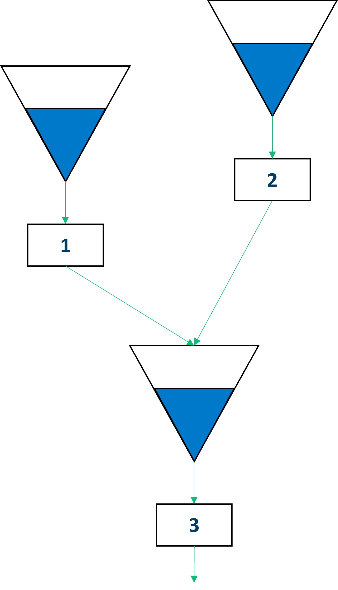
The illustration describes how a situation with two intakes for one station is simulated, using three modules. Module 3 from the illustration is a dummy module with an empty reservoir and no plant.
In theory, the station (module 3) should only be able to receive water from one intake at the same time. In Prodrisk, this is not implemented and the discharge from the intake reservoirs (module 1 and module 2) is decided by the optimization. The maximum discharge from module 3 is set as the larger maximum discharge of the intake reservoirs (module 1 and module 2). The maximum bypass and overflow in module 3 is zero. Bypass and overflow in the intake reservoirs (modules 1 and 2) bypass module 3.
To use the first configuration, the KODE parameter must be set to 100. The two intake modules (module 1 and module 2) must produce water to the station module (module 3), and will leave the code for hydraulic coupling (parameter 9) empty. The station module (module 3) must have all parameters set to 0 except for:
parameter 6: Maximum discharge, which should be set to the larger maximum discharge of the intake reservoirs (modules 1 and 2)
parametere 9: the value 100 as KODE for hydraulic coupling.
parameter 13: Inflow series name.
Configuration 2: Reservoirs coupled through an open tunnel or channel#
In this configuration, 2 or more reservoirs are coupled through an open tunnel or channel. The water is distributed between the reservoirs by optimisation limited by the tunnel capacity. In theory, this could be controlled by a hatch actuator, but this is not implemented in Prodrisk. This configuration is shown below:
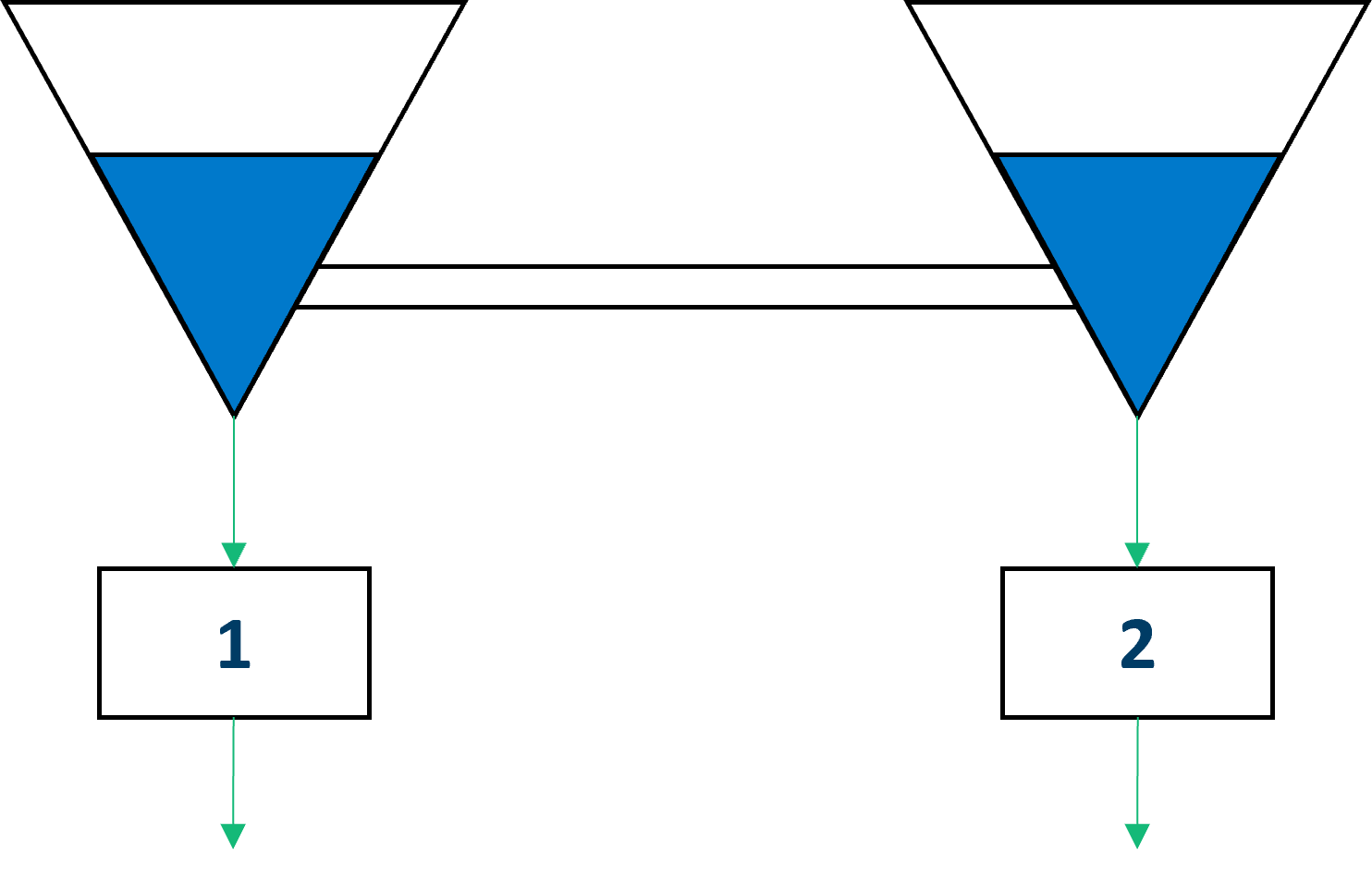
To use the second configuration, the KODE parameter can be set to either 200 og 300 (this is the same configuration in Prodrisk) and the maximum flow capacity must be set to a number in \(m^3/s\). In EOPS, KODE could also be set to 300, but both options are interpreted as the same in Prodrisk.
All reservoirs with the same coupling number belong to the same hydraulic coupling, and the maximum flow capacity can be set separately for each node in the coupling group.
The coupling number is parameter number 10 of the reservoir parameters, called coupling number.
The maximum flow capacity is parameter number 11 of the reservoir parameters, called Maximum flow capacity.
Configuration 3: Reservoirs coupled to a common station with a tunnel or channel between.#
This configuration is a combination of configuration 1 and 2. Here, 2 or more reservoirs are coupled to a common station, like in configuration 1, and additionally, flow between the reservoirs through a tunnel or channel is allowed. The water flow is limited by the tunnel flow capacity

To use the third configuration, the KODE parameter (parameter 9)can be set to either 120 og 130 for all modules: reservoirs (modules 1 and 2) and station (module 3). The reservoirs (modules 1 and 2) must specify the water flow capacity between themselves (parameter 11) and the hydraulic coupling code (parameter 10). The station module (module 3) must have all parameters set to 0 except for:
parameter 6: Maximum discharge, which should be set to the larger maximum discharge of the intake reservoirs (modules 1 and 2)
parameter 9: the value 120 or 130 as KODE for hydraulic coupling
parameter 13: Inflow series name To use the third configuration, the KODE parameter can be set to either 120 og 130.
Hydraulic coupling in the API#
When running Prodrisk through the API, hydraulic couplings are added through the hyraulicType attribute on the module object. The attribute is of type int_array, and consists of three integer parameters:
The first parameter is a code for the type of hydraulic coupling, and corresponds to the KODE parameter discussed above.
The second element is the coupling id, and is identical for modules belonging to the same hydraulic coupling. This corresponds to coupling number discussed above.
The third parameter is the coupling capacity in \(m^3/s\), and corresponds to maximum flow capacity discussed above. Note that this parameter must be set to an integer value.
Example code for the discussed configurations is presented below:
Configuration 1: Modules mod1 and mod2 are coupled to a common station mod3. No direct flow between mod1 and mod2.
mod3.hydraulicType.set([100, 1, 0])
Configuration 2: Modules mod1 and mod2 are coupled through an open channel with a flow capacity of \(15 m^3/s\).
mod1.hydraulicType.set([200, 2, 15])
mod2.hydraulicType.set([200, 2, 15])
Configuration 3: Modules mod1 and mod2 are coupled to a common station mod3. In addition, mod1 and mod2 are coupled through an open channel with a flow capacity of \(15 m^3/s\).
mod1.hydraulicType.set([120, 3, 15])
mod2.hydraulicType.set([120, 3, 15])
mod3.hydraulicType.set([120, 3,  0])